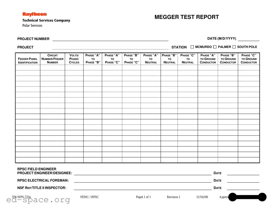
The Megger Test form serves as a vital tool in assessing the insulation resistance of electrical systems, ensuring safety and efficiency in various projects. This comprehensive document includes essential details such as the project number, station, and date, which help to contextualize the testing process. Specific sections of the form are dedicated to identifying feeder panels and circuit numbers, providing clarity on the electrical components being tested. Measurements are taken across different phases, including phase-to-phase and phase-to-neutral readings, which are crucial for diagnosing potential issues. Notably, the form also captures ground conductor readings, allowing engineers to evaluate the overall integrity of the electrical system. The involvement of key personnel, such as the RPSC field engineer and project engineer or designee, is documented, ensuring accountability and traceability in the testing process. This thorough approach not only enhances the reliability of the results but also supports compliance with industry standards, making the Megger Test form an indispensable resource in electrical engineering projects.
MEGGER TEST REPORT
PROJECT NUMBER
PROJECT |
|
STATION |
DATE (M/D/YYYY)
MCMURDO PALMER SOUTH POLE
FEEDER PANEL IDENTIFICATION
CIRCUIT
NUMBER/FEEDER
NUMBER
VOLTS/
PHASE/
CYCLES
PHASE “A”
TO
PHASE “B”
PHASE “A”
TO
PHASE “C”
PHASE “B”
TO
PHASE “C”
PHASE “A”
TO
NEUTRAL
PHASE “B”
TO
NEUTRAL
PHASE “C”
TO
NEUTRAL
PHASE “A”
TO GROUND CONDUCTOR
PHASE “B”
TO GROUND CONDUCTOR
PHASE “C”
TO GROUND CONDUCTOR
RPSC FIELD ENGINEER |
|
|
|
|
|
|
PROJECT ENGINEER/DESIGNEE: |
|
|
|
|
DATE |
|
RPSC ELECTRICAL FOREMAN: |
|
|
|
|
DATE |
|
NSF REP/TITLE II INSPECTOR: |
|
|
|
|
DATE |
|
FEMC / RPSC |
Paget 1 of 1 |
Revision 1 |
11/16//06 |
Approved by Wayne L. Cornell |
||
| Fact Name | Description |
|---|---|
| Project Number | This unique identifier is essential for tracking the specific Megger test conducted at a project site. |
| Location Identifiers | The report specifies locations such as McMurdo, Palmer, and South Pole, which are critical for understanding environmental conditions affecting the test. |
| Date Format | The date must be entered in the format M/D/YYYY, ensuring consistency and clarity in documentation. |
| Voltage and Phase Information | Details about volts, phases, and cycles are recorded, which are vital for assessing electrical system integrity. |
| Field Engineer and Project Engineer | The report includes signatures from the RPSC field engineer and project engineer/designee, confirming accountability and oversight. |
| Regulatory Compliance | This form may be governed by local electrical codes and standards, ensuring that testing meets safety and operational requirements. |
Filling out the Megger Test form requires attention to detail to ensure accurate recording of test results. Follow these steps carefully to complete the form correctly.
Once you have completed the form, double-check all entries for accuracy. This will help ensure that the test results are reliable and can be used effectively in project assessments.
What is the purpose of the Megger Test form?
The Megger Test form is used to document the results of insulation resistance tests on electrical systems. It helps ensure that the electrical equipment is safe and functioning properly. By recording the measurements, engineers can identify potential issues and maintain compliance with safety standards.
What information is required on the Megger Test form?
The form requires several key pieces of information, including the project number, project station, date, feeder panel identification, circuit number, and voltage specifications. It also includes measurements for various phases and neutral connections, as well as signatures from the field engineer and project engineer/designee.
How are the measurements taken during the Megger Test?
Measurements are taken using a Megger, which applies a high voltage to the electrical insulation and measures the resistance. The test results for each phase, as well as the neutral and ground connections, are recorded on the form. This process helps to ensure that the insulation is intact and that there are no leaks or faults.
Who is responsible for completing the Megger Test form?
What should be done if the test results indicate a problem?
If the Megger Test results show low insulation resistance or other issues, immediate action should be taken. This may involve further investigation, repairs, or replacements of faulty components. It is important to address any problems to maintain safety and functionality in the electrical system.
Failing to include the project number or project station can lead to confusion. Each report must clearly identify the associated project to ensure proper documentation and tracking.
Omitting circuit numbers or feeder numbers can result in inaccuracies. Each circuit or feeder must be distinctly labeled to avoid misinterpretation of the test results.
Incorrectly recording voltage or phase information can compromise the integrity of the test. Ensure that all measurements are accurately documented to reflect the actual conditions.
Neglecting to sign off on the report by the field engineer or project engineer can invalidate the findings. Proper signatures are essential for accountability and verification of the test results.
The Megger Test form is an essential document used to assess insulation resistance in electrical systems. Several other forms and documents complement this report, ensuring thorough documentation and compliance with safety standards. Below is a list of these related documents, each serving a specific purpose in the testing and maintenance process.
Each of these documents plays a crucial role in maintaining safety and efficiency in electrical testing. By using them alongside the Megger Test form, professionals can ensure comprehensive evaluations and uphold industry standards.
The Megger Test form shares similarities with several other documents commonly used in electrical testing and reporting. Here’s a concise overview of these documents:
When filling out the Megger Test form, it's essential to ensure accuracy and clarity. Here are some important dos and don’ts to keep in mind:
The Megger Test is a critical procedure used to assess insulation resistance in electrical systems. However, several misconceptions exist regarding its purpose and application. Below are six common misconceptions.
This is not accurate. The Megger Test is essential for both new and existing installations. It helps identify insulation degradation over time, ensuring safety and reliability.
While a high resistance reading generally suggests good insulation, it does not guarantee that there are no issues. Other factors, such as moisture or contamination, can affect performance without showing immediate signs.
Timing is crucial for the Megger Test. It should be conducted when the equipment is de-energized to prevent injury and ensure accurate readings.
This is misleading. Different circuits may require different voltage settings based on their specifications and insulation types. Using the correct voltage is essential for obtaining valid results.
Regular testing is necessary. The insulation condition can change over time due to various factors, including environmental conditions and operational stresses. Routine testing helps maintain safety standards.
While the Megger Test is important, it should be part of a comprehensive maintenance program. Other tests and inspections are also necessary to evaluate the entire electrical system effectively.
When filling out and utilizing the Megger Test form, several important considerations can enhance accuracy and efficiency. Here are some key takeaways to keep in mind:
By keeping these points in mind, you can ensure that the Megger Test form serves its purpose effectively, contributing to the overall safety and reliability of electrical systems.