The Manual J form serves as an essential tool in the HVAC industry, specifically designed to calculate heating and cooling loads for residential buildings. This form is crucial for ensuring that HVAC systems are appropriately sized to meet the unique demands of a home, particularly in Utah's dry climate. It encompasses a comprehensive set of data, including design conditions for heating and cooling, room-by-room load calculations, and specific equipment details. The form requires users to provide information such as outside and inside temperatures, infiltration methods, and the construction quality of the building. Additionally, it accounts for various heat loss and gain factors, including latent and sensible gains, which are critical for determining the overall efficiency of the HVAC system. By adhering to the guidelines set forth in the Manual J form, professionals can ensure compliance with local regulations and optimize energy efficiency, ultimately enhancing the comfort and safety of residential spaces.

Building Services & Civil Enforcement slcpermits.com
451 South State Street, Room 215 |
PO Box 145490 |
Salt Lake City, Utah 84111 |
Salt Lake City, Utah |
Office only |
Updated 12/2012 |
BLD # Received by
Date Valuation
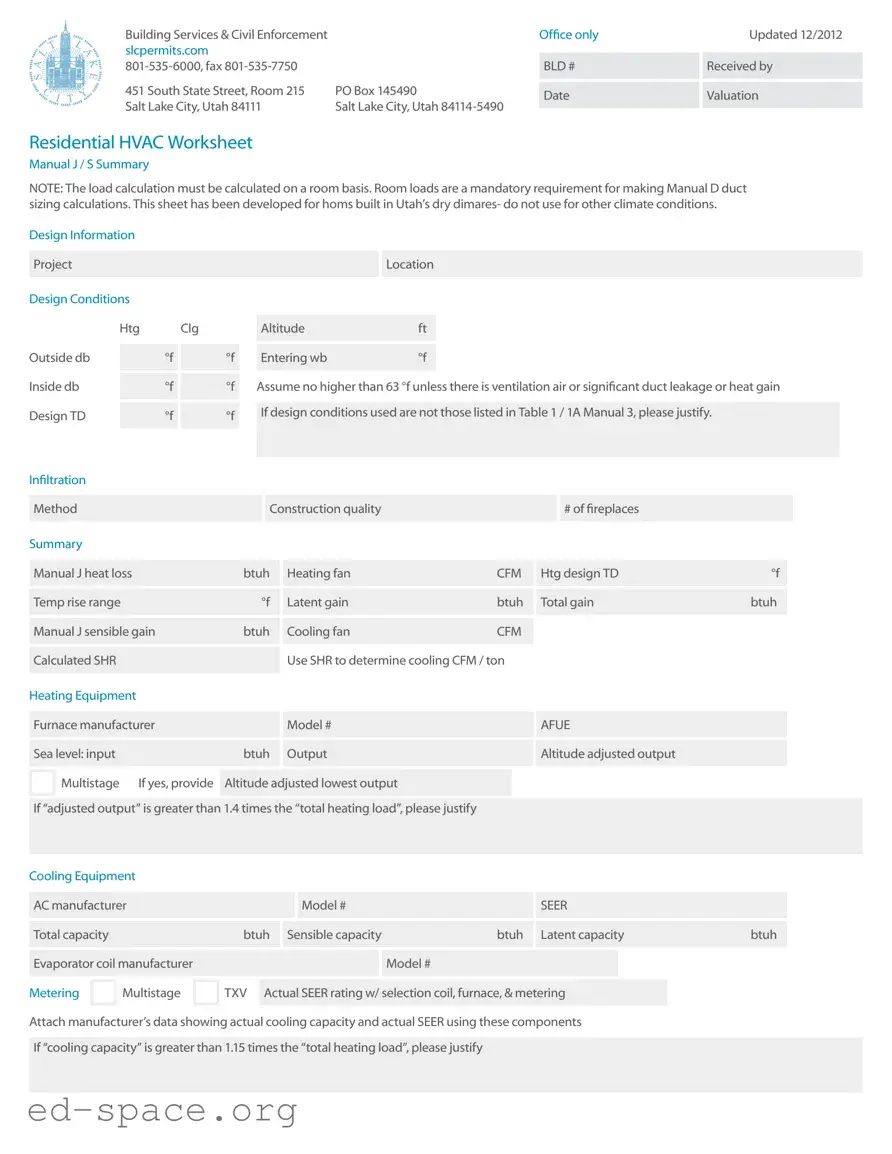
Residential HVAC Worksheet
Manual J / S Summary
NOTE: The load calculation must be calculated on a room basis. Room loads are a mandatory requirement for making Manual D duct sizing calculations. This sheet has been developed for homs built in Utah’s dry dimares- do not use for other climate conditions.
Design Information |
|
|
|
|
|
|
|
|
|
|
|
|
|
|
|
|
|
|
|
|
|
|
|
|
|
|||||
|
|
|
|
|
|
|
|
|
|
|
|
|
|
|
|
|
|
|
|
|
|
|
|
|
|
|
|
|
|
|
|
Project |
|
|
|
|
|
|
|
|
|
|
|
|
|
|
Location |
|
|
|
|
|
|
|
|
|
|
|
|||
|
|
|
|
|
|
|
|
|
|
|
|
|
|
|
|
|
|
|
|
|
|
|
|
|
|
|
|
|
|
|
Design Conditions |
|
|
|
|
|
|
|
|
|
|
|
|
|
|
|
|
|
|
|
|
|
|
|
|
|
|||||
|
|
|
|
|
|
|
|
|
|
|
|
|
|
|
|
|
|
|
|
|
|
|
|
|
|
|
|
|
||
|
|
Htg |
Clg |
|
|
Altitude |
|
|
ft |
|
|
|
|
|
|
|
|
|
|
|
|
|
||||||||
|
|
|
|
|
|
|
|
|
|
|
|
|
|
|
|
|
|
|
|
|
|
|
|
|
|
|
|
|
|
|
|
|
|
|
|
|
|
|
|
|
|
|
|
|
|
|
|
|
|
|
|
|
|
|
|
|
|
|
|||
Outside db |
|
|
°f |
|
|
°f |
|
Entering wb |
|
|
°f |
|
|
|
|
|
|
|
|
|
|
|
|
|
||||||
|
|
|
|
|
|
|
|
|
|
|
|
|
|
|
|
|
|
|
|
|
|
|
|
|
|
|
|
|
||
|
|
|
|
|
|
|
|
|
|
|
|
|
|
|
|
|
||||||||||||||
Inside db |
|
|
°f |
|
|
°f |
|
Assume no higher than 63 °f unless there is ventilation air or significant duct leakage or heat gain |
||||||||||||||||||||||
|
|
|
|
|
|
|
|
|
|
|
|
|
|
|
|
|
|
|
|
|
|
|
|
|
|
|
|
|||
|
|
|
|
|
|
|
|
|
|
|
|
|
|
|
|
|
|
|
|
|
|
|
|
|
|
|
|
|
|
|
Design TD |
|
|
°f |
|
|
°f |
|
If design conditions used are not those listed in Table 1 / 1A Manual 3, please justify. |
|
|
|
|
||||||||||||||||||
|
|
|
|
|
|
|
|
|
|
|
|
|
|
|
|
|
|
|
|
|
|
|
|
|
|
|
||||
|
|
|
|
|
|
|
|
|
|
|
|
|
|
|
|
|
|
|
|
|
|
|
|
|
|
|
|
|
|
|
Infiltration |
|
|
|
|
|
|
|
|
|
|
|
|
|
|
|
|
|
|
|
|
|
|
|
|
|
|
|
|
|
|
|
|
|
|
|
|
|
|
|
|
|
|
|
|
|
|
|
|
|
|
|
|
|
|
|
|
|
|
|
||
|
|
|
|
|
|
|
|
|
|
|
|
|
|
|
|
|
|
|
|
|
|
|
|
|
|
|
|
|
|
|
|
Method |
|
|
|
|
|
|
|
|
Construction quality |
|
|
|
|
|
|
|
|
# of fireplaces |
|
|
|
|
|
||||||
|
|
|
|
|
|
|
|
|
|
|
|
|
|
|
|
|
|
|
|
|
|
|
|
|
|
|
|
|
|
|
Summary |
|
|
|
|
|
|
|
|
|
|
|
|
|
|
|
|
|
|
|
|
|
|
|
|
|
|
|
|
|
|
|
|
|
|
|
|
|
|
|
|
|
|
|
|
|
|
|
|
|
|
|
|
|
|
|
|
|
||||
|
Manual J heat loss |
|
|
|
|
btuh |
|
Heating fan |
|
|
|
|
CFM |
|
Htg design TD |
|
°f |
|
|
|
||||||||||
|
|
|
|
|
|
|
|
|
|
|
|
|
|
|
|
|
|
|
|
|
|
|
|
|
|
|
|
|||
|
|
|
|
|
|
|
|
|
|
|
|
|
|
|
|
|
|
|
|
|
|
|
|
|
|
|
|
|||
|
Temp rise range |
|
|
|
|
to |
|
|
°f |
|
Latent gain |
|
|
|
|
btuh |
|
Total gain |
|
|
btuh |
|
|
|
||||||
|
|
|
|
|
|
|
|
|
|
|
|
|
|
|
|
|
|
|
|
|
|
|
|
|
|
|
|
|
||
|
|
|
|
|
|
|
|
|
|
|
|
|
|
|
|
|
|
|
|
|
|
|
|
|
|
|
|
|
||
|
Manual J sensible gain |
|
|
|
btuh |
|
Cooling fan |
|
|
|
|
CFM |
|
|
|
|
|
|
|
|
|
|
||||||||
|
|
|
|
|
|
|
|
|
|
|
|
|
|
|
|
|
|
|
|
|
|
|
|
|
|
|
|
|
|
|
|
|
|
|
|
|
|
|
|
|
|
|
Use SHR to determine cooling CFM / ton |
|
|
|
|
|
|
|
|
|
|
||||||||
|
Calculated SHR |
|
|
|
|
|
|
|
|
|
|
|
|
|
|
|
|
|
|
|
|
|||||||||
|
|
|
|
|
|
|
|
|
|
|
|
|
|
|
|
|
|
|
|
|
|
|
|
|
|
|
|
|
|
|
Heating Equipment |
|
|
|
|
|
|
|
|
|
|
|
|
|
|
|
|
|
|
|
|
|
|
|
|
|
|||||
|
|
|
|
|
|
|
|
|
|
|
|
|
|
|
|
|
|
|
|
|
|
|
|
|
|
|
|
|||
|
Furnace manufacturer |
|
|
|
|
|
|
|
Model # |
|
|
|
|
|
|
|
AFUE |
|
|
|
|
|
|
|||||||
|
|
|
|
|
|
|
|
|
|
|
|
|
|
|
|
|
|
|
|
|
|
|
|
|
|
|
|
|||
|
|
|
|
|
|
|
|
|
|
|
|
|
|
|
|
|
|
|
|
|
|
|
|
|
|
|
|
|||
|
Sea level: input |
|
|
|
|
|
|
btuh |
|
Output |
|
|
|
|
|
|
|
Altitude adjusted output |
|
|
|
|
||||||||
|
|
|
|
|
|
|
|
|
|
|
|
|
|
|
|
|
|
|
|
|
|
|
|
|
|
|
|
|||
|
Multistage |
|
If yes, provide |
|
|
|
|
|
|
|
|
|
|
|
|
|
|
|
|
|
|
|
||||||||
|
|
Altitude adjusted lowest output |
|
|
|
|
|
|
|
|
|
|
|
|
|
|||||||||||||||
|
|
|
|
|
|
|
|
|
|
|
|
|
|
|
|
|
|
|
|
|
|
|
|
|
|
|||||
|
|
|
|
|
|
|
|
|
|
|
|
|
|
|
|
|
|
|
|
|
|
|
|
|
||||||
|
If “adjusted output” is greater than 1.4 times the “total heating load”, please justify |
|
|
|
|
|
|
|
|
|
|
|||||||||||||||||||
|
|
|
|
|
|
|
|
|
|
|
|
|
|
|
|
|
|
|
|
|
|
|
|
|
|
|
|
|
|
|
Cooling Equipment |
|
|
|
|
|
|
|
|
|
|
|
|
|
|
|
|
|
|
|
|
|
|
|
|
|
|||||
|
|
|
|
|
|
|
|
|
|
|
|
|
|
|
|
|
|
|
|
|
|
|
|
|
|
|
|
|||
|
AC manufacturer |
|
|
|
|
|
|
|
|
|
Model # |
|
|
|
|
|
|
|
SEER |
|
|
|
|
|
|
|||||
|
|
|
|
|
|
|
|
|
|
|
|
|
|
|
|
|
|
|
|
|
|
|
|
|
|
|
||||
|
|
|
|
|
|
|
|
|
|
|
|
|
|
|
|
|
|
|
|
|
|
|
|
|
||||||
|
Total capacity |
|
|
|
|
|
|
btuh |
|
Sensible capacity |
|
|
|
btuh |
|
Latent capacity |
|
btuh |
|
|
|
|||||||||
|
|
|
|
|
|
|
|
|
|
|
|
|
|
|
|
|
|
|
|
|
|
|
|
|
|
|
|
|||
|
|
|
|
|
|
|
|
|
|
|
|
|
|
|
|
|
|
|
|
|
|
|
|
|
|
|
|
|||
|
Evaporator coil manufacturer |
|
|
|
|
|
|
|
|
|
Model # |
|
|
|
|
|
|
|
|
|
|
|
||||||||
|
|
|
|
|
|
|
|
|
|
|
|
|
|
|
|
|
|
|
||||||||||||
|
|
Multistage |
|
TXV |
|
|
|
|
|
|
|
|
|
|
|
|
|
|
|
|
|
|
|
|
|
|
||||
Metering |
|
Actual SEER rating w/ selection coil, furnace, & metering |
|
|
|
|
|
|
||||||||||||||||||||||
|
|
|
|
|
|
|
|
|
|
|
|
|
|
|
|
|
|
|
|
|
|
|
|
|
|
|
|
|
|
|
Attach manufacturer’s data showing actual cooling capacity and actual SEER using these components
If “cooling capacity” is greater than 1.15 times the “total heating load”, please justify
Manual J / S Summary
Instructions
The load information asked for on the summary must be taken from the actual load calculation completed on the project.
Project
Identify project name, lot number- information that matches the plan submitted.
Location
The city or town must be reasonably close to actual location. Software used may not have the specific location in the database.
Outside Dry Bulb, Inside Dry Bulb
Temperature data should be from Table 1 or Table 1A of ACCA Manual J. It is understood that there may be situations where a slight adjustment to this values is necessary. For example; there may be areas in the Salt Lake Valley where the low temperature is historically lower than the airport temperature. If values are adjusted- please justify the adjustment. Provide both heating (htg) and cooling (clg) design temperatures. If inside
or outside design conditions listed are not the same values listed in Manual J, explain why the different values were used.
Entering WB
The entering
63 °f (75 °f dry bulb) relative humidity). A higher wb temperature will result from duct leakage,
air temperature. Use this wb temperature when selecting cooling condenser from manufacturer’s comprehensive data.
Design TD
TD: the temperature difference between inside and outside design temperatures.
Infiltration
Infiltration calculations are based on the Construction Quality. Version 7 of Manual ] uses Best, Average or Poor to evaluate Infiltration. Version 8AE uses Tight,
not be counted. Methods include: Simplified
/Default Method- taken from Table 5A; Component Leakage Area Method- calculating infiltration based on individual leakage points taken from Table 5C of Manual J8; or Blower Door Method, where the actual leakage is based on a blower door test on the home.
Manual J Heat Loss
This is the whole house winter heat loss taken directly from the completed attached Load Calculation. Load must account for all factors such as loss building components as well as loss through infiltration, ventilation, and duct losses.
Heating Fan
Heating airflow typically may be lower than cooling cfm. Adjusted to insure the temperature rise across the heat exchanger falls within the range specified by the manufacturer. Software will often do this calculation and provide a correct heating cfm. See Manual S Section
Manufacturer’s Temperature Rise Range
Range taken from manufacturer’s performance data. Various manufacturers may certify ranges from 20 - 70 °f.
Manual J — Sensible Gain
The whole house summer heat gain taken directly from the completed attached Load Calculation. Load must account for all factors including gain through building components, solar gain, infiltration, ventilation and ducts. Also includes the sensible internal gains from appliances and people.
Manual 3 — Latent Gain
The gains due to moisture in the air. Large latent load are typically from moisture migration into the home from outside in humid climates. People, cooking, plants, bathing and laundry washing can all add to the latent load in a home.
Total Gain
The combined total of the sensible and latent gain. May be referred to as Total Cooling Load.
SHR- Sensible Heat Ratio
Use to determine Cooling cfm per ton. The ratio of sensible heat gain to total heat gain. SHR = Sensible Heat Gain ÷ Total Heat Gain. Recommended air flows: If SHR is below 0.80 select 350 cfm / ton; if SHR is between 0.80 & 0.85 select 400 cfm; if SHR is greater than 0.85, select 450 cfm
/ton. Note: This cfm is not the final cfm; additional adjustment may be required for Altitude. See next item- Cooling Fan.
Cooling Fan
Software used to perform the calculation will typically provide a minimum cfm based on the minimum required size of the equipment. This number may be adjusted to meet specific requirements of the home. Heating and Cooling CFM may or may not be the same. The cooling CFM should be around 450 CFM per ton of cooling in Utah’s dry climates. For higher altitudes, CFM must be adjust up as detailed in ACCA / ANSI Manual S. Mountain location should expect Cooling CFM at 500 CFM per ton and higher.
HEATING
Equipment
List specific equipment to be used. This information is not required on the Load Calculation documents, however it must be provided here to verify equipment sizing against calculated loads.
AFUE
The AFUE (Annual Fuel Utilization Efficiency) listed here will be compared to that listed on plans and on energy compliance documents (RES check or other). It must also match the equipment actually installed in the home.
Sea Level Input
The listed input on the furnace label and in manufacturers’ documentation. Input represents the total amount
of heat in the gas at sea level.
Output
The amount a heat available for discharge into the conditioned space. The input less any vent or stack losses, or heat that is carried out with the products of combustion. May be take from manufacturer’s performance data or calculated using input and furnace efficiency.
Altitude Adjusted Output
This number is the actual output that will be attained after the furnace has been adjusted for efficiency and
Size Justification
Example: If the Total Heating Load = 29954 btuh. A furnace with an adjusted output larger than 45,000 btuh (29954 x 1.5 = 44931) would require an explanation justifying the size.
COOLING
Equipment
List specific equipment to be used. Provide manufacturers comprehensive data for furnace, furnace blower and condenser, with capacities at design conditions highlighted.
Condenser SEER
This SEER (Seasonal Energy Efficiency Ratio) is the listed SEER for this model series, not the exact SEER with components used this system.

Total Capacity
Manufacturers base data is based on ARI Standard 210 / 240 ratings; 95 °f outdoor air temperature, 80 °f db / 67 °f wb entering evaporator. As the Design Conditions
are different than this standard, refer to manufacturers expanded ratings for capacities at actual design conditions. Total capacity is the latent and sensible capacity at design conditions
Sensible Capacity
The sensible only capacity from the manufacturer’s expanded data at design conditions.
Manual D Calculations & Summary
Project
Friction Rate Worksheet & Steps
1Manufacturer’s Blower Data
External static pressure (ESP) |
IWC |
CFM |
|
|
|
Latent Capacity
The latent only capacity from the manufacturer’s expanded data at design conditions. NOTE: One half of the excess latent capacity may be added to the sensible capacity.
Evaporator Coil Make and Model #
List the exact model number for the evaporator coil used this system. If coil is from a different manufacturer than the condenser is used, provide data from both manufacturers verifying actual performance.
Expansion / Metering
Provide the specific metering used- orifice or TXV (thermostat expansion valve). If the manufacturer has several options, list the option used.
Actual SEER Rating
Attach manufacturers’ documentation or ARI report showing actual cooling capacity, and actual SEER using the components used this system. Indoor air handler / furnace blower must be included in this documentation. Do not use ARI (ARHI) data for actual sizing.
Size Justification
If cooling capacity is 15% greater than the calculated Cooling load explain. High latent (moisture) loads can be listed here. Special requirements particular to the customer may also be noted here.
2Device Pressure Losses
Evaporator |
Supply register |
.03 |
Other device |
|
|
|
|
|
|
|
|
|
|
|
Air filter |
Return grill |
.03 |
Total device losses (DPL) |
IWC |
|
|
|
|
|
3Available Static Pressure (ASP)
ASP = ( ESP - DPL ) IWC
4Total Effective Length (TEL)
Supply side TEL |
ft |
|
Return side TEL |
ft |
|
|
|
|
|
Total effective length (TEL) = supply side TEL + return side TEL ft
5Friction Rate Design Value (FR)
FR = ( ( 100 x ASP ) / TEL ) IWX / 100’
Mechanical Sizing
Name of contractor / designer
Phone Fax
Address
Permit # Lot #
This friction rate (FR) calculated in Step 5 is the rate to be used with a duct calculator or a friction chart for the duct design on this project.
Attach at a minimum, a one line diagram showing the duct system with fittings, sizes, equivalent lengths through fitting and duct lengths.
Vent height (base of duct to roof exit) ft

Boiler or furnace input rating |
btu |
|
|
|
|
btu |
|
|
|
|
|
Connector rise |
ft |
|
|
|
|
Connector run |
ft |
|
|
|
|
Connector size |
in |
|
|
|
|
Orifice size |
in |
|
|
|
|
Water heater input rating |
btu |
|
|
|
|
btu |
|
|
|
|
|
Connector rise |
ft |
|
|
|
|
Connector run |
ft |
|
|
|
|
Connector size |
in |
|
|
|
|
Orifice size |
in |
|
|
|
|
Total heat input of all appliances |
btu |
|
|
|
|
Vent size for the system |
in |
|
|
|
|
Combustion air size |
in² |
|
|
Signature |
|
Boiler or furnace #2 input rating btu
Connector rise ft
Connector run ft
Connector size in
Orifice size in
Water heater #2 input rating btu
Connector rise ft
Connector run ft
Connector size in
Orifice size in
Attach a complete gas pipe layout & sizing detail to the plan or permit application.
If a manifold is used to connect the appliances on the horizontal, it shall be the same size as the vent.
To the best of my knowledge, I certify that the information contained within this document is true, correct, and meets the requirements of the 2009 International Mechanical Code and International Fuel Gas Code.
Date
Mechanical Sizing Worksheet |
|
b |
Example: SLC has a 17% |
||
|
|
factor. On a 100,000 Btu furnace you |
|||
Materials needed to fill out this form are the |
|
|
multiply 100,000 x .83 = 83,000 Btu’s |
||
|
c |
On the vent sizing this becomes |
|||
International fuel gas Code and the Questar |
|
||||
Recommended Good Practices Book. |
|
|
the fan min. The fan max is the |
||
VENT SIZING |
|
|
listed input rate example fan |
||
|
|
min = 83 and fan max = 100 |
|||
1 |
Vent height is measured from the |
|
d |
The Btu to ft³ conversion number for |
|
|
draft diverter or appliance vent |
|
|
SLC is 890 and the specific gravity of |
|
|
outlet to the top of the vent cap. |
|
|
the gas is .60. Divide the new input |
|
2 |
Connector rise is the height of the vent |
|
|
rating by 890, 83,000 = 93.258 ft³. 890 |
|
|
|
|
|||
|
connector from the appliance outlet |
|
e |
Take the ft³ of input and divide it by the |
|
|
to the center of the tee in the vent at |
|
|
number of burners on the appliance, |
|
|
the point of connection to the vent. |
|
|
this will give you the ft³ / burner. Then |
|
3 |
Connector run is the horizontal distance |
|
|
use the orifice tables in the Questar |
|
|
|
handbook to determine the orifice size. |
|||
|
from the appliance vent outlet to the vent. |
|
|
||
|
|
|
Example if you have 4 burners: 93.258 |
||
|
|
|
|
||
4 |
Go to the International Fuel Gas |
|
|
ft³ / 4 burners = 23.315 ft³ / 1 burner. |
|
|
Code Chapter 5. Sizing is done to |
|
|
Match as close as possible to the |
|
|
the appropriate gamma table . |
|
|
Orifice table in the handbook. In this |
|
5 |
The gamma tables are in Btu and not ft³ |
|
|
sample the orifice size would be (49) |
|
2 |
Use the International Fuel Gas Code and the |
||||
|
International Mechanical Code to complete |
||||
|
|
|
|||
1 |
See Questar handbook for a |
|
the vent sizing and the combustion air |
||
|
sizing. See Chapter 5 IFC for the rules and |
||||
|
formula and the required conversion |
|
|||
|
|
the tables to fill out this portion of the form. |
|||
|
numbers. To complete this form: |
|
|||
|
|
ICBO also has available a commentary on |
|||
|
|
|
|||
|
a Input is |
|
the mechanical code that contains a step- |
||
|
1000’ in elevation. |
|
|||
3The International Mechanical Code commentary also contains examples to size the gas pipe. You must show the pipe lengths, the Btus and the volume of each appliance and show the size of each length of pipe. All tables necessary to size gas pipe are also contained in the International Fuel Gas Code, and in the Questar handbook.
4For Salt Lake City use:
a890 Btu per ft³
bA multiplier of .83
cSpecific gravity of .60
dCombustion air is computed at 1 in² per 3,000 Btu of input of all fuel burning appliances in the room. One duct upper 12” of the room.
EQuestar gas has a training program available to all persons and contractors.
| Fact Name | Description |
|---|---|
| Purpose | The Manual J form is used to calculate heating and cooling loads for residential HVAC systems, ensuring proper equipment sizing and energy efficiency. |
| Room-Based Calculation | Load calculations must be performed on a room-by-room basis. This approach is essential for accurate duct sizing calculations, as outlined in Manual D. |
| State-Specific Use | This form is specifically developed for homes built in Utah's dry climate. It is not suitable for use in other climate conditions. |
| Governing Laws | In Utah, the Manual J form is governed by the 2009 International Mechanical Code and the International Fuel Gas Code. |
| Data Requirements | Accurate temperature data for both indoor and outdoor conditions must be sourced from Table 1 or Table 1A of the ACCA Manual J, with justifications provided for any adjustments. |
Filling out the Manual J form requires careful attention to detail and accurate data entry. This process ensures that the heating and cooling loads for a residential project are calculated correctly. Follow these steps to complete the form efficiently.
What is the Manual J form and why is it important?
The Manual J form is a standardized document used to calculate the heating and cooling loads for residential buildings. It is essential for ensuring that HVAC systems are appropriately sized for the specific needs of a home. Accurate load calculations help prevent issues such as inadequate heating or cooling, which can lead to discomfort and increased energy costs. By using the Manual J form, contractors can design systems that operate efficiently and effectively, ultimately benefiting homeowners.
How is the Manual J form completed?
Completing the Manual J form involves gathering specific data about the home, including its location, design conditions, and construction quality. A detailed load calculation must be performed on a room-by-room basis, considering factors like insulation, window types, and infiltration rates. The results of these calculations are then entered into the form, which helps in determining the appropriate size and type of heating and cooling equipment needed for the home.
What factors influence the heating and cooling load calculations?
Several factors influence the heating and cooling load calculations, including the home's geographical location, construction materials, insulation levels, and the number and type of windows. Additionally, the presence of fireplaces, the home's orientation, and the amount of ventilation also play significant roles. Each of these elements can impact how much heat is lost in winter or gained in summer, making it crucial to consider them all during the calculation process.
What is the significance of the design temperature difference (TD) in the Manual J form?
The design temperature difference (TD) is the difference between the inside and outside temperatures that the HVAC system must maintain. This value is critical because it directly affects the heating and cooling loads. By accurately determining the TD, professionals can ensure that the HVAC system is capable of maintaining comfortable indoor conditions, even during extreme weather conditions.
Why is it necessary to perform load calculations on a room basis?
Performing load calculations on a room basis is necessary to achieve a more precise understanding of how each space in the home will respond to heating and cooling demands. Different rooms may have varying insulation levels, window sizes, and usage patterns, which can significantly affect their individual heating and cooling needs. This detailed approach ensures that each room receives the appropriate amount of conditioned air, promoting overall comfort and efficiency.
What happens if the Manual J calculations are not accurate?
If the Manual J calculations are not accurate, it can lead to several issues. An undersized HVAC system may struggle to maintain comfortable temperatures, resulting in increased energy costs and potential system failure. Conversely, an oversized system can lead to short cycling, where the system turns on and off frequently, causing wear and tear and reducing efficiency. Both scenarios can negatively impact the comfort of the home and the longevity of the HVAC equipment.
How does the Manual J form relate to other HVAC documents?
The Manual J form is closely related to other HVAC documents, such as Manual D and Manual S. While Manual J focuses on load calculations, Manual D addresses duct design, ensuring that air distribution systems are appropriately sized and configured. Manual S deals with equipment selection, ensuring that the chosen HVAC systems can meet the calculated loads. Together, these documents create a comprehensive approach to HVAC system design, promoting efficiency and comfort in residential buildings.
Inaccurate Temperature Entries: One common mistake is entering incorrect outside and inside temperature values. It's crucial to use the data from the appropriate tables in the Manual J form to ensure accuracy. Adjustments should only be made when justified.
Neglecting Room-by-Room Load Calculations: Many individuals forget that load calculations must be done on a room-by-room basis. Failing to do so can lead to improper HVAC sizing and inefficiencies.
Ignoring Infiltration Method: Not specifying the method used to calculate infiltration can lead to significant errors. Each method has its own criteria, and it’s important to note which one was used for the calculations.
Omitting Equipment Details: Some people leave out critical information about the heating and cooling equipment. This includes manufacturer details and efficiency ratings, which are necessary for verifying proper sizing against calculated loads.
Misunderstanding Sensible Heat Ratio (SHR): Failing to calculate the SHR correctly can affect the cooling airflow. This ratio is essential for determining the right cooling CFM per ton, and miscalculations can lead to inadequate cooling.
Overlooking Justification for Adjustments: When adjustments are made to temperature or equipment outputs, it’s essential to provide justifications. Neglecting this step can lead to questions or rejections from reviewers.
The Manual J form is an essential document for calculating heating and cooling loads in residential buildings. However, it is often accompanied by several other forms and documents that provide additional information and support for HVAC system design and installation. Below is a list of some commonly used documents alongside the Manual J form.
These documents work together to create a comprehensive approach to HVAC design, ensuring that the systems installed are efficient, effective, and compliant with relevant standards. Properly completing and submitting these forms can lead to better performance and comfort in residential spaces.
When filling out the Manual J form, it's important to follow specific guidelines to ensure accuracy and compliance. Here are four key dos and don'ts:
Misconceptions about the Manual J form can lead to confusion and errors in HVAC calculations. Here are ten common misconceptions along with clarifications:
Filling out the Manual J form is an essential step in ensuring that HVAC systems are properly sized for residential buildings. Here are some key takeaways to keep in mind:
Understanding these key points can lead to more efficient HVAC system design and improved comfort in residential spaces.